In the domain of robotics and automation, precision-controlled mechanical movements have ushered in a revolutionary wave across diverse industries, spanning from manufacturing to healthcare. Thanks to the advent of cost-effective microcontrollers (Arduino) and easily accessible programming tools, enthusiasts and hobbyists now have the means to create their own Bluetooth-controllable robotic arm using an Arduino board, servo motors, and a motor driver.
Robotic arms have found their way into an extensive array of applications, from industrial automation to even Pick and Place assembly lines. The ARA (Arduino Robotic Arm) now, from the comfort of your own home, you can construct a Robot Arm mounted on a 2WD Arduino car kit.
This tutorial will serve as an illuminating guide on how to create an Arduino-powered Robotic Arm, replete with wireless control and programmability facilitated through a custom-build Android application. Within the application's interface, individual servos or axes of the robot arm can be manually maneuvered using dedicated buttons. Notably, this robot car encompasses two primary functions: a 2WD car mode and the control of a robotic arm. This integration is achieved through the utilization of two DC motors and a robotic arm. The robotic arm itself is presented through both a 3D-designed model (designed from scratch) and a physically assembled iteration.
Also check our previously built Robotic Arm projects using different microcontrollers:
At first, the thought of building a robotic arm might sound complex and gruesome. But after learning the physics and kinematics behind it and going more in-depth to the topic. You will understand that it is not that hard.
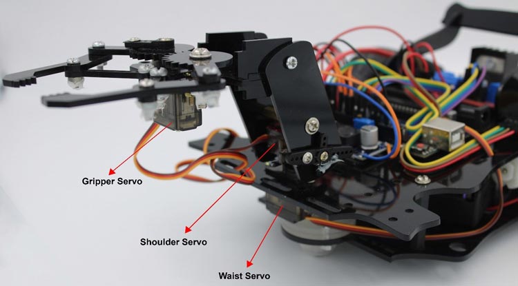
This robotic arm consists of 3 servo motors 1 for Gripper and 2 for Arm joints movement. This means that the DOF (degree of freedom) for this robot is 2. The angle and position of the Arm depends on the kinematics.
Kinematics is the science that considers the motion of an object (robot) without cares for the cause of that motion. Kinematics studies the position, velocity, acceleration, and other higher derivatives of position with respect to time. Therefore, the study of kinematics refers to all geometrical and time-based properties of motion.
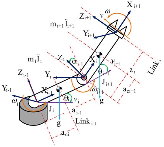
An arm robot manipulator is a set of links connected by joints, the lowest part is called the based, and the end part is called end-effector. The number of joints and how it moves define the degree of freedom (DOF). The joints are characterized as revolute or prismatic joints. Below fig shows 2 DOF robot consists of all revolute joints. A typical applied in industries robot has 5 or 6 joints. In this project, the kinematics and dynamics are derived from 2 DOF for the sake of simplicity.
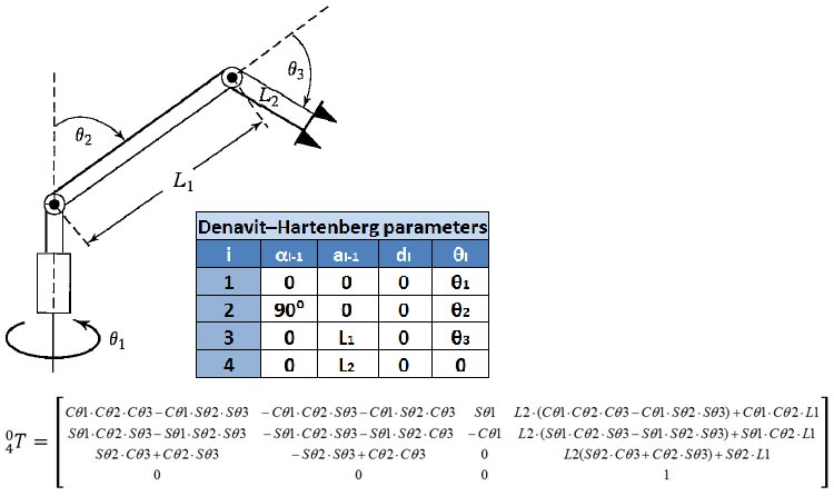
Forward kinematics involves utilizing a robot's kinematic equations to calculate the position of the end-effector based on given joint parameter values, which in this context are the positions of the servo motors. In the sketch of the robotic arm below, you can visualize the Denavit-Hartenberg parameters, an essential component in this process. Additionally, the derived forward kinematic equations for the robotic arm are presented.
While an alternative approach was ultimately pursued, one not reliant on matrices, the derived equations remain valuable for those interested in exploring different methodologies. It's important to note that 'C' represents cosine and 'S' represents sine.
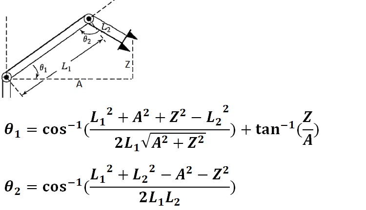
By solving the Inverse Kinematics equations, we can precisely control the movement and orientation of the robotic arm's end-effector. These equations provide us with the necessary angles for each joint to achieve a desired position in space. The figure below visually breaks down the variables that play a crucial role in these equations, allowing us to translate mathematical concepts into practical arm movements.
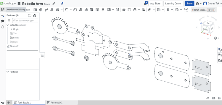
I created the custom robotic arm specifically for this project, and you can see screenshots of the CAD design I made using onshape, as well as the actual mechanical arm I built, in the images below. If you're interested in recreating this project or incorporating my design into your own work, I've included the CAD .dxf files, which you can download from here.
For constructing the arm, I used laser-cut acrylic parts. However, if you have access to a 3D printer, you can also use that. If you opt for the 3D printing route, you'll need to open the files in SolidWorks, convert them to STL format, and save them. To do this, open any part, click 'Save As,' and choose STL as the file format.
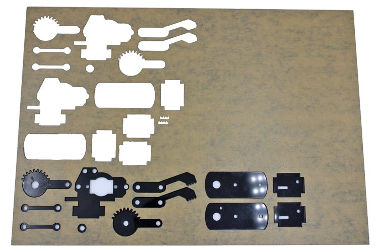
Here's a visual representation of what the laser-cut acrylic sheet will look like.
Arduino robot arms, much like other robot arms, are commonly evaluated based on their degrees of freedom (DOF). This term refers to the count of rotational joints integrated into the robot's design. The concept of DOF is interchangeable with the term "axes," a familiar term in this context. For instance, a 2DOF (2 Axis) robot arm is equipped with two distinct axes enabling specific motion.
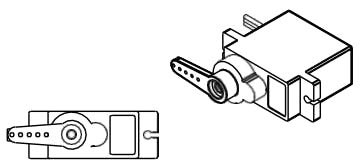
This robotic arm arrives in a flat-pack state, requiring minimal soldering for assembly and activation. It incorporates two MG90 servos, enabling two degrees of movement. Notably, it can adeptly grip lightweight objects using the gripper.
We have utilized an acrylic sheet cut with a laser to create a Robotic Arm for our project. The sheet has been precisely cut to accommodate all the necessary fittings and components, allowing for easy assembly using screwdrivers.
Before starting the assembly, we need to adjust the angle adjustment of the servo motors. Otherwise, your robotic Arm will not work properly.
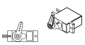
To begin, attach the Servo Arm to the servo by carefully aligning and securing it in place. We can manually calibrate and adjust the servo motor angle but some time manually calibration is not accurate or may not be possible. so you can calibrate your servo motors using the provided code #1. Refer to the circuit diagram mentioned below and connect your servo motors to Arduino pins 5, 6, and 3 accordingly. Upload the provided code #1 to your Arduino board, which will facilitate the calibration process. Failing to execute this step may result in unstable performance of your robot.
By ensuring proper alignment and calibration of the servos, you lay the foundation for a stable and well-functioning robot.
Angle values for robotic arm movements
No.
Servo type
Angle of rotation on servo(in°)
Information